Welding Reference Charts & Settings
Shop-reference pages for common welding lookups: symbols, rod selection, amperage ranges, wire sizes, and starting settings by process.
100%
Free to Use
6
Calculators
Shop-reference pages for common welding lookups: symbols, rod selection, amperage ranges, wire sizes, and starting settings by process.
AWS standard welding symbols, notations, and blueprint markings for understanding welding specifications.
Stick electrode types, classifications, tensile strength, and applications for SMAW (stick) welding processes.
MIG amperage, voltage, and wire feed settings for different material thicknesses and wire types.
SMAW electrode amperage settings for different rod sizes, metal types, and joint positions.
TIG amperage, shielding gas, and filler rod sizes for aluminum, stainless steel, and carbon steel.
MIG and TIG wire diameters, cross-sectional areas, and recommended amperage ranges for each size.
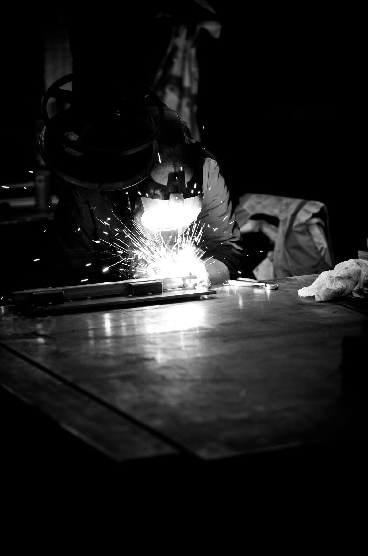
These welding charts are most useful when the job is already defined and you need a practical starting setup. They help answer the questions that come up constantly in fabrication and repair work: what amperage range fits the rod, where MIG settings should start, what TIG setup is reasonable, and what gas choice makes sense before you strike the first arc.
A welding symbol chart matters because plenty of bad welds start with a print being read wrong. Fillet size, groove prep, arrow side, field weld marks, and finish notes all change what is actually required. On shop work, one misread symbol can turn into rework long before anyone questions the bead itself.
A stick welding chart helps match rod type, rod diameter, and amperage to the work. E6010, E6011, and E7018 do not run the same, and field conditions change the feel fast. Wind, dirty steel, position, and generator power all matter. The chart gets you close, but puddle control and slag behavior are still what tell you if the setting is really right.
A MIG welding settings chart is useful when you need a quick reference for voltage, wire feed speed, gas mix, and thickness range. On thinner material, slightly too much heat can blow edges out or warp the panel. On heavier sections, a cold setup may leave a decent-looking bead with poor fusion. That is why MIG settings always need to be checked against joint fit-up and not just the thickness of the base metal.
A TIG welding chart is mostly about control. Stainless, aluminum, thin wall tubing, and visible finish work all demand a steadier setup than typical production MIG. Tungsten size, gas flow, filler choice, and amperage range have to work together. If the setup is off, the problem shows up fast as contamination, poor puddle control, or excess heat in the part.
Mild steel, stainless, aluminum, and cast material all react differently, and position changes everything. Flat bench welding is not the same as vertical repair or overhead field work. Gas choice changes the result too. A 75/25 mix behaves differently from straight CO2, and TIG on aluminum is a different setup from TIG on stainless. These welding reference charts work best as setup guides, not as fixed rules that ignore the actual job.